In modern energy management and smart grids, electricity meters are no longer simply “mechanical meters” that record electricity consumption. Today’s smart meters are powerful data acquisition terminals capable of monitoring numerous parameters in real time, including voltage, current, power factor, and frequency.
However, to realize the value of this data, smart energy meters must be able to “communicate” with gateways, PLCs (Programmable Logic Controllers), or cloud management systems. This requires communication protocols. This article will provide an in-depth analysis of the three most commonly used core communication technologies in smart grids: RS485, Modbus RTU, and MQTT.
1. Foundational Building Block: RS485 (Physical Layer)
First, it’s important to clarify a common misconception: RS485 is not a communication protocol, but rather a physical layer interface standard. It specifies how signals are transmitted through physical cables.
If we compare data transmission to sending letters, then RS485 is the road and postal vehicle. It only cares about delivering the letter from point A to point B; it doesn’t care what language is written on the letter.
Core Features of RS485
Differential Signal Transmission: RS485 uses the voltage difference between two signal lines (usually called A and B) to represent logic “1” and “0”. This design gives it extremely strong immunity to common-mode interference.
Long-Distance Transmission: Industrial environments are complex and subject to severe electromagnetic interference. RS485 can transmit up to 1200 meters (or even further, depending on the baud rate), making it ideal for factories, buildings, and photovoltaic power plants.
Multi-Point Topology (Bus System): Multiple devices can be connected simultaneously on a single RS485 bus, significantly reducing cabling costs.
2. Industry Standard: Modbus RTU (Protocol Layer)
With the “roads” laid by RS485, devices need a common language to communicate, and this is where Modbus RTU comes in. It is one of the most widely used protocols in industrial and power monitoring fields.
Modbus RTU uses a master-slave architecture. On a single bus, there can only be one “master” (such as a data acquisition unit, PLC, or PC), and multiple “slave” devices (i.e., electricity meters). Slave devices do not actively communicate; they only respond when the master sends a request.
Modbus RTU Message Structure Analysis
Modbus RTU is a compact binary protocol. A typical data frame usually contains the following four parts:
Slave Address: 1 byte. Used to specify which electricity meter should receive this instruction (e.g., 0x01).
Function Code: 1 byte. Tells the electricity meter what operation to perform. For example, 0x03 represents reading a register (reading data), and 0x06 represents writing to a single register (changing settings).
Data Area: Variable length. Contains the starting address of the register to be read, the number of registers to read, or the specific value to be written.
CRC (Cyclic Redundancy Check): 2 bytes. A cyclic redundancy check code used to ensure data is not corrupted during long-distance transmission.
Example Application: > An energy management system (master) sends a 0x03 command to energy meter #1 (slave) every 15 minutes to read the A-phase voltage register. Upon receiving this command, energy meter #1 immediately replies with the current voltage value (e.g., the binary representation of 220.5V), and then the bus remains silent, awaiting the next query.
Moving to the Cloud: MQTT (Internet of Things Protocol)
Modbus RTU performs perfectly in LANs and industrial fields, but in today’s distributed energy, smart park, and cross-regional meter reading scenarios, we need to aggregate massive amounts of electricity data to a cloud platform. At this point, the LAN limitations of Modbus RTU become apparent, and we need MQTT.
MQTT (Message Queuing Telemetry Transport) is a lightweight IoT communication protocol based on a publish/subscribe model. It runs on top of the TCP/IP protocol stack and is specifically designed for remote devices with low network bandwidth and unstable networks.
Core Roles of MQTT
Client (Electricity Meter or Gateway): Can publish data (e.g., uploading electricity consumption) and subscribe to commands (e.g., receiving remote power outage control).
Broker (Cloud Middleware): Responsible for receiving all published messages and distributing them to the necessary subscribers based on the “Topic”.
Unique Advantages of MQTT
Event-Driven: Unlike Modbus’s “no-questions-only” approach, MQTT allows electricity meters (or edge gateways) to proactively push messages to the cloud when specific events occur (e.g., transformer overload, power outage alarms), resulting in extremely high real-time performance.
Extremely low bandwidth overhead: MQTT message headers are very small (minimum only 2 bytes), significantly saving bandwidth costs in large-scale meter networking.
Decoupling: Cloud systems (such as visualization dashboards, billing software, and maintenance apps) only need to subscribe to relevant topics from the MQTT Broker to obtain meter data, without interference between systems.
4.How Do The Three Work Together?
In actual smart metering or energy management projects, these three technologies are usually not isolated but rather combined and each performs its specific function.
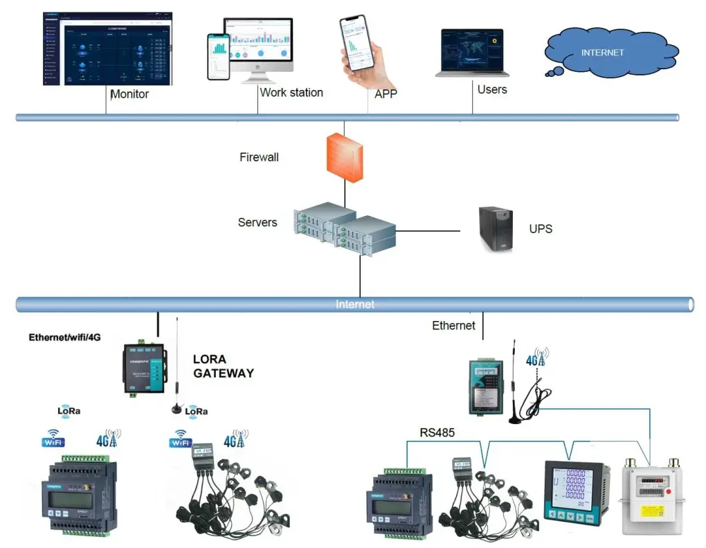
A typical IoT smart meter architecture is as follows:
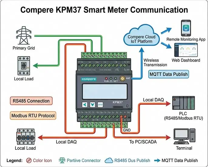
Local Layer: Multiple smart meters are connected in series via RS485 twisted-pair cables.
Data Collection Layer: A smart gateway installed in the field acts as a Modbus master, periodically polling these meters via the Modbus RTU protocol to obtain raw binary data such as current, voltage, and energy.
Protocol Conversion: The gateway parses and combines the received Modbus binary data, converting it into structured JSON format.
Cloud Layer: The gateway connects to the internet (via 4G, WiFi, or LoraWAN) and uses the MQTT protocol to publish the JSON data to an MQTT Broker in the cloud, allowing the final energy management software to perform big data analysis, billing, and fault prediction.
5.How to Choose? (Selection Guide and Decision Model)
Scenario 1: Purely Localized Control and Data Acquisition (Selection: RS485 + Modbus RTU)
If your project is a standalone, closed system, data does not need to be uploaded to the internet.
Typical Scenarios: Factory workshop power distribution cabinets, shopping mall internal meter reading, PLC control cabinets, cold storage environment monitoring.
Reasons for Selection: Simple structure and extremely low cost. You only need to buy a meter with an RS485 interface and connect it in series with a PLC or local industrial touchscreen (HMI) using two wires. No complex network, IP address, or cloud server configuration is required; it is stable and reliable with no subsequent data charges.
Scenario Two: Remote Cross-Regional Management and Cloud Big Data (Selection: MQTT Architecture)
If your electricity meters are distributed in different locations, or if you need to remotely view and manage them via a mobile app or web interface.
Typical Scenarios: Smart parks, distributed photovoltaic power stations, energy consumption management for nationwide chain stores, charging pile billing systems.
Rationale for Selection: Traditional Modbus cannot directly penetrate complex enterprise firewalls or mobile cellular networks (such as 4G/WiFi). MQTT, based on TCP/IP, is naturally suitable for internet transmission. It ensures that meter data is securely and in real-time transmitted across the network to the cloud server.
Summary
In the construction of modern intelligent power management systems, RS485, Modbus RTU, and MQTT are not mutually exclusive competing technologies, but rather a golden partnership at different levels of the communication architecture, each with its own specific function and perfect complementarity.
RS485 is the “path” (physical layer): It utilizes differential signaling to solve the hardware connection problems of high electromagnetic interference, long transmission distances, and multi-device networking in industrial environments.
Modbus RTU is the “local language” (protocol layer): Relying on the RS485 channel, it achieves stable and accurate data exchange between local devices through a compact binary structure and a rigorous master-slave query-response mechanism.
MQTT is the “airborne express” (IoT layer): It transcends the limitations of local area networks, bridging the last mile for field data to reach modern cloud-based big data platforms with its lightweight publish/subscribe mechanism and proactive reporting features.
📌 Final Selection And Implementation Recommendations:
Pure Local Area Monitoring: If data only needs to be transmitted to the PLC, touchscreen, or local computer on-site, and the meters are centralized, directly choose the RS485 + Modbus RTU architecture. This is the most economical, mature, and cost-free solution in the long run.
Distributed Remote Cloud Migration: If electricity meters are geographically dispersed (e.g., in smart parks, multi-location chain stores, or photovoltaic power plants), and data needs to be connected to a cloud platform or mobile app, the MQTT protocol is introduced.
The Most Scalable Golden Combination: For most medium to large-scale projects, a hybrid architecture of “local samrt meter + RS485 + gateway + cloud MQTT” is recommended. This design retains the advantages of low cost and high stability of local meters while providing the entire system with unlimited cloud scalability and intelligent possibilities.