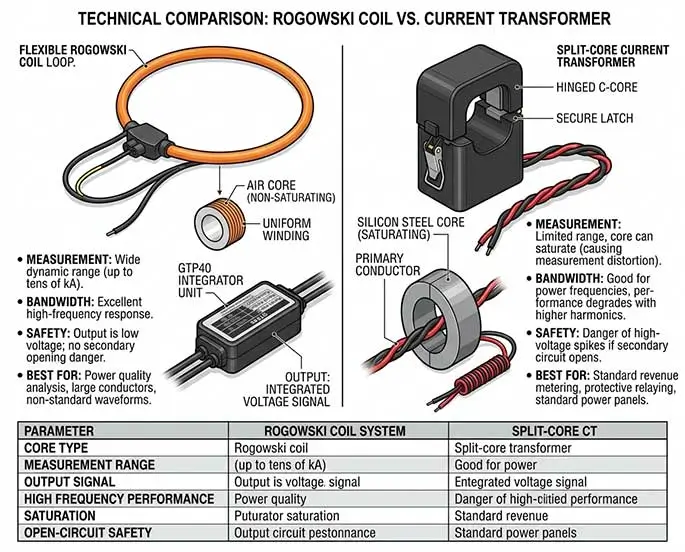
In power distribution network energy-saving retrofits, factory energy efficiency management (EMS), and high-energy-consuming equipment monitoring projects, “uninterrupted power supply and no wiring disconnection” are stringent requirements for on-site construction. Against this backdrop, Rogowski coils and split-core current transformers (CTs) have become the two mainstream choices.
While both can be installed in an open-loop configuration, they differ fundamentally in their electromagnetic mechanisms, signal processing, and performance under extreme conditions. This article, drawing on firsthand engineering experience, provides a high-information-density selection guide, from underlying logic to application pain points.
KPM37 Wireless Energy Meter With Rogowski coilsStructure and Physical Characteristics: Flexible Hollow Core vs. Rigid Iron Core
The manufacturing process and physical form of both directly determine their adaptability to the physical environment of the installation site.
Split-core Current Transformer (CT)
Based on traditional electromagnetic induction design. Internally, it contains a slidable closed iron core (usually made of silicon steel sheets, microcrystalline silicon, or permalloy), and the outer shell is mostly made of rigid engineering plastic.
Field pain points: As the rated current increases (e.g., above 2000A), the volume and weight of the iron core increase exponentially, with a single unit weighing several kilograms. In densely packed low-voltage cable branches or compact switchgear, rigid CTs often cannot be installed due to limited space and lack of mounting options.
Rogowski Coil
This is a coreless, air-core coil. It uniformly winds the conductor onto a non-ferromagnetic material (such as a plastic or rubber skeleton).
Field advantages: It appears as a flexible, bendable loop. Regardless of the measured current, the coil’s cross-sectional area remains almost constant, and the overall weight is only tens to hundreds of grams. In renovations of older residential areas and in narrow cable trenches, the flexible coil can be easily threaded through and locked like a braided rope.
Underlying Working Principle: Differential Sampling vs. Flux Ratio
The difference in measurement mechanisms is the fundamental reason for the significant difference in their electrical performance.
1. Open-Type CT: Traditional Proportional Converter
Open-type CTs follow the standard transformer dual-winding model. The primary bus current generates alternating magnetic flux in the closed core, inducing a proportionally reduced current signal in the secondary coil (common turns ratios are 5 amps, 1 amp, or 100 mA in miniature CTs).
Unavoidable Physical Defect—Magnetic Saturation: The permeability of the core is finite. When the primary side encounters starting inrush current, large short-circuit current, or severe high-order harmonics, the magnetic flux density in the core reaches its physical limit, resulting in magnetic saturation. Once saturated, the secondary waveform will exhibit severe clipping distortion, leading to malfunctions of protection devices or complete distortion of metering instrument data.
2. Rogowski Coil: Current Change Rate Sampling + Hardware Integration
The Rogowski coil has the same permeability as air. It measures not the absolute amplitude of the current, but the differential of the current with respect to time, i.e., the rate of change of the current.
Unsaturation Characteristics and Integrator Dependence: Since it has no iron core, the Rogowski coil has no possibility of magnetic saturation, and its input and output exhibit a strictly linear relationship over an extremely wide range. However, because the output is a millivolt-level differential voltage signal, a dedicated integrator must be used for hardware or digital integration to restore it to a standard 0-5V, 4-20mA, or 1A signal.
In-Depth Horizontal Evaluation of Technical Parameters
In technology selection, it is not enough to simply look at the accuracy level; safety and losses under extreme operating conditions must also be considered.
| Core Comparison Dimension | Rogowski Coil | Split-core Current Transformer (CT) |
|---|---|---|
| Magnetic Saturation Risk | No Risk (High linearity up to 100kA+) | High Risk (Typically saturates when exceeding 120% of rated current) |
| Dynamic Measurement Range | Extremely wide (A single coil can cover 10A ~ 100kA) | Narrow (Typically limited to 10% ~ 120% of rated current range) |
| Secondary Open Circuit Danger | Absolutely Safe (Only outputs millivolt-level voltage) |
Extremely Dangerous (Strictly prohibited to open circuit; otherwise induces thousands of volts, causing arcing and destruction) |
| High-Frequency Response (Bandwidth) | Extremely Excellent (Hz level to several MHz, capable of capturing nanosecond-level transients) | Narrow (Typically 50Hz/60Hz, iron loss increases sharply at high frequencies) |
| System Power Consumption & Supply | Independent Power Supply Required (Integrator usually requires DC 24V power supply) |
Passive/Active Optional (The CT itself is passive and requires no external power supply) |
| Frequency Limitation | AC Only (No induction to static DC) | AC Only (Except for specialized Hall-effect split-core CTs) |
| Comprehensive Deployment Cost | Higher (Requires an additional set of active integrator hardware) | Lower (Mature technology, standard products offer high cost-performance ratio) |
Frontline Engineering Experience: Selection Pitfalls and Application Recommendations
In actual engineering implementation, blindly pursuing new technologies or simply trying to save money can lead to pitfalls. Please perform precise matching based on the following typical scenarios:
Scenario A: Rogowski coils are recommended.
Cable retrofitting with limited space (e.g., old substations): When the copper busbar spacing is less than 10 mm, or multiple thick cables are intertwined and twisted, rigid current transformers (CTs) simply cannot close. In this case, utilizing the wiring advantages of flexible Rogowski coils is the only solution.
High current and impulsive load monitoring: Such as monitoring the starting current of electric arc furnaces, submerged arc furnaces, and large motors in steel plants. In these scenarios, the current can easily reach thousands or even tens of thousands of amperes, accompanied by a large number of harmonics. Traditional CTs saturate instantly, while Rogowski coils, combined with integrators, can accurately reconstruct the complete current waveform.
Full-band power quality analysis: If the project requires monitoring grid harmonics above the 50th order, or needs to capture transient inrush currents caused by lightning strikes or switch switching, the ultra-wide frequency response bandwidth of Rogowski coils is essential.
Scenario B: Open-type current transformers are recommended.
For standard factory energy consumption or commercial building sub-metering: In low-voltage distribution circuits with current below 800 amps and relatively ample space, open-type current transformers (CTs) offer excellent cost-effectiveness.
For passive or unavailable auxiliary power: Rogowski coil integrators are electronic components and must be connected to a 24V or 220V power supply. If the distribution box at the renovation site cannot provide auxiliary power, or cannot accommodate an integrator rail, a passive open-type CT should be selected directly.
For connecting to older pointer meters or specific protection devices: If the downstream secondary instrument only accepts a standard 5-amp ratio current, and there is no extra space or budget for installing a conversion module at the instrument end, choosing a 5-amp output open-type CT is the most convenient and seamless alternative.
Quick Selection Checklist
Consider space: Choose Rogowski coils in narrow spaces, and open-type CTs in spacious spaces.
Consider the current rating: For high current, surge current, and high harmonic loads, choose a Rogowski coil; for mains frequency, small to medium current, and constant loads, choose an open-face current transformer (CT).
Consider the power supply: Choose a Rogowski coil if it can provide auxiliary power to the integrator; choose an open-face current transformer if passive monitoring is required.